

Deep Dive into Database Design - Part 1
Mastering Advanced Concepts and Best Practices in Database Architecture

This is an extended guide on the theoretical and academic approach to database design. While databases have had an explosion of adoption in the modern world and their implementation transmitted down to software developers building sophisticated web applications, mobile applications, APIs, and other systems requiring storage capabilities, databases had humble beginnings in formal academic institutions that defined their overall design as a rigorously mathematical language. Most developers are only familiar with the database interaction languages and tools that they touch every day, like MySQL and Postgres (among many others), but what most are less familiar with is how to properly implement database design in a way that is technically sound and logically correct in an intention to maximally reduce or eliminate redundancy, duplication and out-of-sync commonalities.
This is an extensive guide that looks at database design starting from an academic approach and then transitions to practical examples using relational databases. I approach this subject very technically, defining a clear strategy for arriving at a database design implementation, but only after we have completed steps like requirements planning, ER diagrams, schema development and schema normalization.
This guide is split into two sections:
Part 1 covers database systems, database design and the relational model. Examples are provided to explore the different aspects of these topics in detail.
Part 2 covers the database design refinement process. Once we’ve achieved an initial design, the objective becomes to maintain data integrity and constraints while maximally eliminating redundancy.
Contents
Part 1 (This Post) - Initial Database Design
Introduction to database systems
Database design
The relational model
Part 2 (Next Post) - Normalization and Refined Database Design
Schema normalization
Schema refinement
Functional dependencies
Normal forms
Going Deeper - BCNF
Going Deeper - 3NF
Properties of decompositions
Normalization
Synthesis
Section 1 - Intro to database systems
We’re going to begin by defining a set of terms:
A database is a collection of data
Entities are the main objects in a database that typically correspond to the core tables
Examples of entities include … students, faculty, courses, classrooms
Relationships are the “links” (associations) between entities
An example of a relationship is a student object enrolling into a course object
Relationships are also commonly their own tables (initially, at least) although during the schema normalization and refinement process, they are often combined and merged with entity tables to avoid the duplication of information in our storage system

File systems vs DBMS
A database manage system (DBMS) is just an application software available on computers
In the earliest of times in the evolution of computers, databases were initially file systems - you would utilize files to store data. This is in fact how a lot of non-technical users continue to save information, like passwords or personal notes and it works in a very friendly form.
The difference between databases and file systems is that databases are a specialized type of storage solution that focuses explicitly on being hyper-optimized to the storage and retrieval of data.
In contrast, file systems focus more on their functionality related to user experience and interactivity
To further define some terms:
A database language, like MySQL, is simply that syntax that is used to communicate between some application and the underlying database system.
A database system is just a live server, running in the background on your computer or a cloud server, that takes SQL commands as inputs and returns structured data as output
Since a database system is a background process on computers, the most direct interaction a developer was with it is through the command line, where the database system comes with a set of commands/functions to be able to interact with the underlying database system, databases and stored data
With that in mind, the purpose of a DBMS is to provide a GUI and extended functionality to make the interaction with the underlying database system simpler and more efficient - after all, remembering and writing CLI commands can be quite cumbersome especially on repeatable tasks
Advantages of DBMS
Data independence
DBMS provides an abstraction view to hide the data representation from storage
Efficient data access
Techniques used for faster data access
Integrity and security
With integrity constraints, it acts like a mathematical model that is proof-safe
Concurrent access and crash recovery
A DBMS schedules concurrent access
Describing a DBMS
A DBMS allows users to define the data to be stored in terms of a data model
A data model just refers to how data is represented conceptually or practically
As you will see, there are different types of data models
Some data models act as an intermediary way to represent a database during the design process - such as a semantic data model
Other data models act as the final way a database is represented by the actual database system - such as a relational database model, which apply to all relational database systems
A semantic data model is a more abstract, high-level data model that makes it easier for a user to come up with an initial description of the data
A widely used semantic data model is the ER model / ER diagram
A database design starts with a semantic model and moves towards a relational model (one that can be implemented on the DBMS)

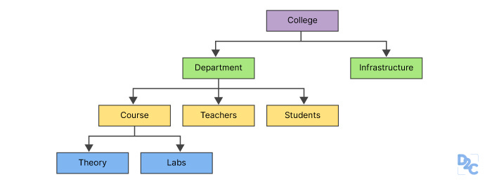
Example of a data model for a university database:
Steps
Semantic data model - Develop an ER diagram
The ER diagram serves as the conceptual/semantic data model
This is an initial design of our database to identify all the entities and relationships
Relational model - SQL tables
The relational model serves as an iterative representation of the final database representation
The relational model has the final form in schema format
The ER Diagram:

The Relational Model:
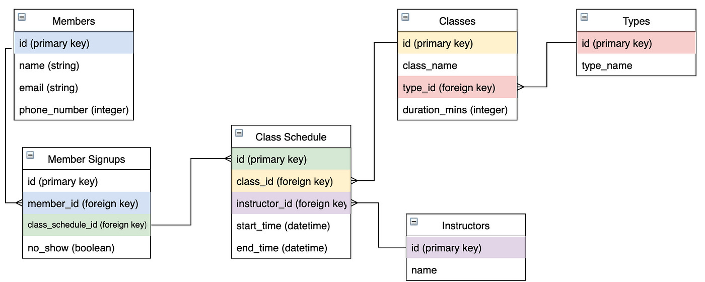
The Relational model
The description of data in terms of a data model is called a schema
The schema for a relation specifies
The name of the relation
The name of each field / attribute / column
The data type of each field (string, integer, boolean, etc)
After a schema is defined, we need to define rules that apply to what is allowed and not allowed for this data:
The rules are known as constraints, or integrity constraints
Integrity constraints specify the conditions for which the records in a relation are valid or invalid
Abstraction in a DBMS
Returning now to our database definition - we will define three stages in our database design process:
The conceptual design
Focuses on the high level structure of the database
This is an intermediary representation, completely independent of the actual database system
The objective is to capture the complete set of requirements
The physical design
This involves the actual implementation of the database
We translate the high-level design into specific technical designs - for we store/retrieve data
This is more related to the efficiency considerations related to storing/retrieval
The external design
This focuses on how the database is interacted with from the user’s perspective
This refers more to the definition of views for our development team or APIs and their relation actions for the applications that we develop for end-users

The database description consists of a schema at each of these three levels of abstraction.
A data definition language (DDL) is used to define the external and conceptual schemas.

1 | Conceptual schema
Also known as the logical schema
Describes stored items in terms of the data model of the DBMS
Describes entities and relationships
The objective is to capture the overall requirements through the following:
Entity-Relationship Model (ER Model)
The most common tool used in conceptual design is the ER diagram
This is a visual representation of the entities (objects), their attributes, and relationships between them
Entities and Attributes
These are the main objects (entities) in the database and their properties (attributes)
Properties are anything that describe the entity or relationship object
Relationships
Defines how entities are related to one another
Example
Students (
  sid: string,
  name: string,
  login: string,
  age: integer,
  gpa: real
)
Faculty (
  fid: string,
  fname: string,
  sal: real
)
Courses (
  cid: string,
  cname: string,
  credits: integer
)
Rooms (
  nw: integer,
  address: string,
  capacity: integer
)
Enrolled (
  sid: string,
  cid: string,
  grade: string
)
Teaches (
  fid: string,
  cid: string
)
Meets_In (
  cid: string,
  rno: integer,
  time: string
)
2 | Physical schema
Describes additional storage details
Summarizes how the relations in the conceptual schema are actually stored on secondary storage devices
Storage devices are most often disks and tapes
Considerations
Storage Structures
Deciding on how data will be stored in the database
This includes data files, indexes, and storage allocation
Indexes and Access Methods
Creating indexes to improve query performance and defining how data will be accessed
Data Partitioning and Clustering
Organizing data in a way that optimizes performance and storage use
Performance Tuning
Ensuring the database meets performance requirements by adjusting parameters and structures

3 | External schema
Allow data access to be customized and authorized at the level of users or groups
There can be only 1 conceptual and 1 physical schema, but there can be multiple external schemas
Consists of a collection of 1 more views and relations from the conceptual schema

Section 2 - Database design
The entity-relationship (ER) data model allows us to describe the data involved in terms of objects and relationships
Used to develop an initial database design
The ER model is used in a phase called conceptual database design
Steps in Database Design
Requirement analysis
Understand what data is to be stored
What apps must be built on top
What operations are most frequent
Conceptual database design
Develop a high-level description of the data to be stored in the database and its constraints
This step involves the ER model (semantic model)
Logical database design
Convert the conceptual database design into a database schema in the data model of the DBMS
Converting the ER schema into a relational database schema
Schema refinement
Analyze the collection of relations in the relational database schema to identify problems and refine it
Theory of normalization - relations-restructuring
Physical database design
Performance criteria and requirements
Clustering of tables and creation of views
Application and security design
Key constraints
Key constraints are defined on associations between entities and relationships:
Participation:
TOTAL - This means that every record must have participation in the relationship table
PARTIAL - This means that some records in either entity may not exist in the relationship table
Relationships
Many to Many
1 to Many
Many to 1
1 to 1
Weak Entities
Some data item that would not make sense to keep if some other item didn’t exist
Dependency of data upon a strong entity
The owner entity set and weak entity set must participate in a 1 to many relationship set
The weak entity must have TOTAL participation
Class Hierarchies
Entity sets can be set as super and subclasses
Attributes of a subclass are inherited from the superclass
The symbol is a triangle with the “IS A” label

Two types of constraints for class hierarchies:
Overlap: OVERLAP / NO-OVERLAP
Whether two subclasses are allowed to contain the same entity
The default is NO-OVERLAP
Covering: COVER / NONE
Whether the entities in the subclasses collectively include all entities in the superclass
Do all instances defined in the subclasses make up the entire set of the entities in the superclass?
Example of OVERLAP constraints
Employee superclass
Hourly_Employees and Contract_Employees are the subclasses
Could X be both of these subclasses? No
Hourly_Emplyees and Senior_Employees are the subclasses
Could X be both of these subclasses? Yes
Denoted as “Contract_Employees OVERLAPS Senior_Employees”
Example of COVERING constraints
Motor_Vehicles superclass
Motorboats and Cars subclasses
Motorboats and Cars COVER Motor_Vehicles
Any entity in the superclass must be at least one entity in the subclasses
Aggregation
A relationship between a collection of entities and relationships
Aggregation allows that a relationship set can participate in another relationship set (with an entity)
A DASHED BOX is drawn around the relationship set that acts like an entity

Section 3 - The relational model
The relational model is simple and elegant:
A database is a collection of one or more relations
Each relation is a table with rows and columns

The data definition language (DDL) is a subset of features inside SQL that is standard for creating, manipulating, and querying data in a relational DBMS.
An important component of a data model is the set of constructs it provides for specifying conditions that must be satisfied by the data - known as integrity constraints
This is the process of converting an ER diagram into a relational database schema.
Relational model
A relation consists of a relation schema and a relation instance
The schema describes the relations name, the name of each field/attribute and the domain of each field.
The relation instance is a table
The relation schema describes the column heads for the table
Example
Students (sid: string, name: string, login: string, age: integer, gpa: real)
An instance of a relation is a set of rows/tuples/records.

A relational database is a collection of relations with distinct relation names.
The relational database schema is the collection of schemas for the relations in the database.
Integrity constraints
An integrity constraint is a condition specified on a database schema
It restricts data that can be stored in the instance
If the database instance satisfied all the ICs, it is a legal instance
A DBMS enforces ICs and only permits legal instances
Types of constraints
Key constraints
Foreign key constraints
General constraints
1 | Key constraints
A key constraint is a statement that a certain minimal subset of the fields of a relation is a unique identifier
A set of fields that uniquely identifies a tuple to a key constraint is called a candidate key (or just key)
Candidate key
Two distinct rows/tuples in a legal instance cannot have identical values in all the fields of a key
No subset of the set of fields in a key is a unique identifier for a tuple (thus, it’s minimal)
Out of all available candidate keys, one is identified as the primary key.
In SQL
… UNIQUE (name, age) …
… CONSTRAINT StudentsKey PRIMARY KEY (sid) …
A key is created using the UNIQUE constraint
A primary key is declared using the PRIMARY KEY constraint
CONSTRAINT constraint_name is used to name a constraint
When the constraint is violated, the constraint_name is returned to identify the error
CREATE TABLE Students(
  sid CHAR(20) ,
  name CHAR (30) ,
  login CHAR(20) ,
  age INTEGER,
  gpa REAL,
  UNIQUE (name, age),
  CONSTRAINT StudentsKey PRIMARY KEY (sid)
)
2 | Foreign key constraints
With foreign key constraints, deletes that eliminate the primary key originator tuple will violate the foreign key constraint of another, and therefore it should be rejected
These constraints are specified with ON DELETE and ON UPDATE
Example
# Enrolled(studid: string, cid: string, gTade: string)

CREATE TABLE Enrolled(
  studid CHAR(20) ,
  cid CHAR(20),
  grade CHAR(10),
  PRIMARY KEY (studid, cid),
  FOREIGN KEY (studid) REFERENCES Students
)
3 | General constraints
The main three constraints are:
Domain
Primary key
Foreign key
Additional constraints can be added using assertions or code outside SQL.
Enforcing ICs
For domain / PRIMARY KEY / UNIQUE constraints:
If an INSERT/DELETE/UPDATE causes a violation, it is rejected.
Every potential violation is checked at the end of each SQL statement execution, although it can be deferred to the end of a transaction execution
For foreign key constraints:
We discuss referential integrity enforcement steps taken by the DBMS
INSERT does not cause any problems
UPDATE and DELETE can cause violations of referential integrity
Suppose there is a Students table with a primary key and an Enrolled table that has that key as a foreign key.
Three basic questions:
What should we do if an Enrolled row is inserted with a student_id that does not appear in the Students table?
In this case, the INSERT is rejected
Question 2 - What do we do if a Students row is deleted?
Question 3 - What do we do if the PK value of a Students row is updated?
The options for these are the same as for Q2
Three options for Question 2 / 3:
Delete all the rows in the Enrolled table that refer to the deleted Students row.
Disallow (reject) the deletion of the Students row if an Enrolled row refers to it.
Set the student_id column to the some default value for every Enrolled row that refers to the deleted row in the Students table
For every row in Enrolled that refers to it, set the student_id column to null
However, if Enrolled has a PK that includes student_id (foreign key), this can become a violation and therefore this fourth option is not always available
SQL allows us to choose any of the four options on the DELETE and UPDATE commands.
CREATE TABLE Enrolled(
  studid CHAR(20) ,
  cid CHAR(20) ,
  grade CHAR(10),
  PRIMARY KEY (studid, dd),
  FOREIGN KEY (studid) REFERENCES Students
    ON DELETE CASCADE
    ON UPDATE NO ACTION
)
What the table above states is that:
When the student_id in Students is deleted, you should also delete the Enrolled record that refers to that id.
When the student_id in Students is updated, no change should be made in the Enrolled record
ON DELETE / ON UPDATE can be specified for each foreign key
The default option is NO ACTION (on, both, DELETE / UPDATE) - this means that the action is to be rejected
“ON UPDATE NO ACTION” can be omitted since it is using the default
If ON UPDATE used CASCADE, this means that the student_id in Enrolled would be updated for all items that refer to the PK student_id that was changed
Another option is “ON DELETE SET DEFAULT”
The default would be specified in the table creation query (beow)
Another option is “ON DELETE SET NULL”
But in this case, the foreign key property cannot be part of the PK of this table
CREATE TABLE Students … sid CHAR(20) DEFAULT “53666”In this circumstance, a DEFAULT PK does not make sense, so it would make more sense to CASCADE
Transactions and Constraints
A program running against a database is called a transaction.
It can contain several statements - queries, inserts, updates
By default, if any violation occurs during the statement, every action within the statement is rolled back
Example ‘Transaction’:
Consider the following: Students and Courses are two tables that require each other as foreign key attributes. But the creation (INSERT) of one is violated since neither can be created without the representation of the other.
In this case, you need to defer the checking of the constraint and perform it as a transaction
CREATE TABLE Students (
  sid CHAR(20) ,
  name CHAR(30),
  login CHAR (20) ,
  age INTEGER,
  honors CHAR(10) NOT NULL,
  gpa REAL
  PRIMARY KEY (sid),
  FOREIGN KEY (honors) REFERENCES Courses (cid)
)

CREATE TABLE Courses (
  cid CHAR(10),
  cname CHAR (10) ,
  credits INTEGER,
  grader CHAR(20) NOT NULL,
  PRIMARY KEY (dd)
  FOREIGN KEY (grader) REFERENCES Students (sid)
)
At the end of an INSERT statement, add the following:
INSERT … SET CONSTRAINT ConstraintFoo DEFERRED;SQL allows a constraint to be in DEFERRED or IMMEDIATE mode:
A constraint in deferred mode is checked at commit time (default)
Querying Data
SELECT …
FROM …
WHERE …
Example
SELECT S.name, E.cid
FROM Students S, Enrolled E
WHERE S.sid = E.studid AND E.grade = 'A'
Logical database design
Local database design is the design that transitions from an ER design to relational design:
Entities
Each entity set becomes a table
Each attribute in an entity set becomes an attribute of the table
Relationships
A relationship set, like the entity set, is mapped to a relation in a relational model
Attributes include:
The PK attributes of each participating entity as FK fields
The descriptive attributes of the relationship set
The collection of non-descriptive attributes is a superkey
If there are no key constraints (like 1-to-many), this set is a candidate key
Example
CREATE TABLE Reports_To (
    supervisor_ssn CHAR(11),
    subordinate_ssn CHAR(11),
    PRIMARY KEY (
        supervisor_ssn,
        subordinate_ssn
    ),
    FOREIGN KEY (supervisor_ssn) REFERENCES Employees (ssn),
    FOREIGN KEY (subordinate_ssn) REFERENCES Employees (ssn)
)
Relationships with Key Constraints
CREATE TABLE Manages (
    ssn CHAR(11),
    did INTEGER,
    since DATE,
    PRIMARY KEY (did),
    FOREIGN KEY (ssn) REFERENCES Employees,
    FOREIGN KEY (did) REFERENCES Departments
)
Since each Department has one unique Employee, the PK of Manages is set as the employee_id (ssn).
Given that department_id (did) is the PK of Manages, the Departments table could potentially consume the entire Manages table and they could be combined together into one table.
This approach eliminates the need for a separate Manages relation
The drawback is the space wasted if several departments have no managers, since the ssn (employee_id) would be NULL for a lot of entries inside Departments_Manages if there are many departments with no managers
CREATE TABLE DepLMgr (
    did INTEGER,
    dname CHAR(20),
    budget REAL,
    ssn CHAR(11),
    since DATE,
    PRIMARY KEY (did),
    FOREIGN KEY (ssn) REFERENCES Employees
)
In this modified table, ssn (employee_id) can be NULL - which indicates departments with no managers.
Relationships with Participation Constraints
Suppose that every requirement must have one manager (TOTAL participation) of the Departments in the Manages table.

CREATE TABLE DepLMgr (
    did INTEGER,
    dname CHAR(20),
    budget REAL,
    ssn CHAR(11) NOT NULL,
    since DATE,
    PRIMARY KEY (did),
    FOREIGN KEY (ssn) REFERENCES Employees ON DELETE NO ACTION
)
DepLMgr states that the ssn (employee_id) field cannot be NULL. Therefore each record in this table must reference a record from the Employees table.
“NO ACTION” specifies that Employee records cannot be deleted while they are referenced by this table.
They are rejected
Participation constraints (TOTAL / PARTIAL) are captured using the “NOT NULL” statement at a table creation.
Constraints that require assertions: Having each Employees entity manage at least one department
Weak Entity Sets
Always a 1 to many relationship
It must have a key constraint and TOTAL participation
The weak entity only has a partial key
When the owner entity is deleted, all the weak entity references must be also deleted
CREATE TABLE Dep_Policy (
    pname CHAR(20),
    age INTEGER,
    cost REAL,
    ssn CHAR(11),
    PRIMARY KEY (pname, ssn),
    FOREIGN KEY (ssn) REFERENCES Employees ON DELETE CASCADE
)
The simple difference is the “ON DELETE CASCADE” to entries in Employees.
Class Hierarchies
There are two approaches to handling hierarchies:
Each each entity set to a relation for both the superclass and the subclasses
Example - Creating relations for Employees, Hourly_Employees, and ContractEmployees
A constraint to consider is that if the superclass is deleted, the delete must be cascaded to the subclass
Just create relations for the subclasses, which will contain all the fields, including those of the superclass
Approach 1 is general and always applicable.
The drawback is the requirement of JOINs when you are examining multiple sub-tables
Approach 2 requires full COVERING constraints in the subclasses, since the superclass is not represented alone.
Also, is there are OVERLAP constraints, you are storing a lot of potential duplicate data
Queries must examine two different queries to search for items too
Views
A view is a table whose rows are not explicitly stored in the database
Data is computed as needed from a view definition
CREATE VIEW B - Students (name, sid, course) AS
SELECT S.sname, S.sid, E.cid
FROM Students S, Enrolled E
WHERE
    S.sid = E.studid
    AND E.grade = 'B';
Then the view can be used as a base table.
We can DELETE/UPDATE items from Students directly through B-Students
If a change to Students affects GoodStudents, by default SQL will allow the update of GoodStudents - but using “WITH CHECK OPTION”, you can prevent changes that will affect the view table
We can insert a GoodStudents row by inserting a row into Students and using NULL for the values of Students that do not appear in GoodStudents